Walls made with rammed earth encased in steel-belted rubber (recycled automobile tires).
Structure for Off-Grid Housing.


Download this Tire Wall Support File


Typical walls are about two feet four inches (2‘-4”) wide, the diameter of a tire, filled with rammed earth. Tires are places in staggered manner, similar to adobe blocks, concrete blocks, and brick. A typical roof span is about 16 feet, constructed of wood vigas. The interior surfaces are plastered with mud plaster, similar to adobe walls.
This wall is built about seven to ten feet high, to provide roof slope for drainage to the rear. Total weight at the bottom of the wall, at floor level, is approximately 3,600 pounds maximum. Since the width is about 2’-4”, the pressure on the soil is about 1550 pounds per square foot.
If a concrete footing were to be used, a minimum width footing of 16 inches would give a total load pressure of just 2,700 psf. This footing width is just over half the wall width. In my opinion, the soil pressures under the 2’-4” walls should cause no excessive settlements, at 1,550 psf.
Since the pressure under the walls is so low, it eliminates the need for a wider footing, built of concrete.
In my opinion, the other purposes of concrete footings are to provide a base to begin constructing the stem wall and to provide some ability to spread loads along the wall in case there is a region of softer soil under the wall. if the tire walls are used only on sites where the soil is uniformly firm and undisturbed, the concrete footing is not necessary. The walls and the soil need only to be protected from moisture incursion.
Examples of adobe houses, churches, and schools built on simple foundations of stones can be found around the state. Where these buildings have been kept dry and the foundations have been kept dry, they last for many years.
When the house is built on dry competent natural soil, and is kept dry, it is my opinion that the concrete foundation may be omitted.
Very truly yours,
Kenneth D. DeLapp, P.E. Structural Engineer
Overview
BUILDING SITE ANALYSIS
Good site drainage is very important in preserving the stability of tire walls – especially where earthcliffs are used. Controlled drainage both surface and subsurface must be provided to insure that the foundation area remains dry throughout the life of the building. There shall be no standing water within 50 feet of building. Landscaping of adjacent grounds shall be designed to detour all surface water runoff around the building. it is also necessary to determine if any underground springs exist on or near the site.
TIRE WALLS
In the same tradition as the thick adobe walls southwestern Indians built centuries ago, the walls of this massive solar home are designed to keep the interior cool during the day by absorbing the sun’s rays until nightfall when the energy begins to come out of the walls and heat the home. non-traditional, however, is the use of tires to support the adobe walls. These tires are packed with adobe earth and stacked flat in a brick-like manner. A sand, straw, and adobe mix is then used to pack the spaces between the tires and as a plaster to cover the wall surface. The walls serve an ecological purpose by providing a use for otherwise discarded tires and an economic purpose in creating the needed mass for passive solar heating and energy conservation.
Based on the tests conducted for this analysis and the calculations performed, it is felt that the rammed earth-filled tire walls used in Earthship construction will provide safe and dependable support for the structure. The laterally braced walls have sufficient strength from their massive structure and internal tire – to – tire friction to resist the sliding and overturning pressures imparted to the walls from the outside.
Concrete footings below the tire walls are not necessary because the typical width of the tire wall, 2’-4”, disperses the weight in such a way that the pressure under the walls is so low that settlement should not occur. (See Section IV. “Soil Loads” and Evaluation Letters from Delapp Engineering in Part I).
The tire walls are capable of resisting an equivalent fluid pressure of 36 pounds per cubic foot (pcf) in a free-standing condition. However, there should be no lateral pressures exerted against the tire walls until they are restrained via the U configuration or battered tire wall at the closed ends and the wall returns at the open ends. With these restrains in place and the roof diaphragm completed, the tire walls will be capable of resisting lateral earth pressures as great as 128 pcf.
Frost protection must be provided for the bottom courses of tires at the short wall supporting the inclined windows and for the tires atop the earth cliff. This can be achieved either through berming soil against the tire walls of through burial of the bottom course. The required depth of bury or berming can be obtained from your building official.
For more thorough analysis of tire wall construction, see Buckhorn Geotech’s engineering evaluation of Weaver residence included in this report and analysis by DeLapp Engineering (see evaluation letters).
BATTERED NORTH TIRE WALL
After analysis of the new wall configuration shown in sk-1 and sk-2, Buckhorn Geotech concluded that straightening the formerly curved back wall will not adversely affect the tire wall strength nor its ability to withstand lateral earth pressures so long as the top of the wall is laterally braced by the roof system. This bracing can be achieved through either the use of a beam constructed against or on top of the tire wall, a soil anchor or tieback into the fill embankment, or through a direct connection between the tire wall and the roof system. in the latter case, the roof must be constructed with sufficient strength and rigidity to transfer the lateral load to the north-south shear walls.
Battering of the tire wall will increase the stability of earth cliff by moving the wall load away from the cliff face. It will also enhance the wall’s ability to resist overturning forces applied through the retained soil. However, the height of the battered wall should not exceed 6 feet without special provisions for backfilling. Where a height greater than 6 feet is desired, the fill should consist of granular material compacted to 90 to 93 percent of its Modified Proctor Density. The fill should be placed in concert with the wall construction that each overhanging tire rests both on the tires below and on the compacted fill. It should be noted that over-compacting of the fill adjacent to the tires could damage the wall. Care must also be taken to insure that the battered wall interlocks at each course where it adjoins the north-sough walls. Blocks should not be used in the interlocking area. If blocks are needed, they should be placed in the north-south walls at least two tires away from the joint. Also, the blocks should be staggered so that they are not placed one atop the other nor should they connect on the diagonal.
SOIL LOADS
It is recommended that you have your building site investigated by a soils engineer to insure that it is suitable for construction of an Earthship. The worst case soil loads for various snow loads are shown at the end of this section of the generic Earthship calculations and can be determined using the chart below.

Use local snow load requirements to calculate minimum Soil Bearing Capacity (Soil Load) required for your building site. Have soils engineer verify that adequate bearing capacity is provided at site.
The bottom tires of a tire wall should be seated on dry, firm, undisturbed soil with a bearing capacity meeting the requirements shown above. The soil should not contain organic debris or any pockets or lenses of soft yielding material.
ROOF ATTACHMENT
The attachment of the roof to the top of the tire wall is important to provide the lateral bracing needed to stabilize the tire wall. To insure an adequate connection, the anchor bolts tying the tires to the concrete grade beam should extend at least 7 inches intot he concrete cavity carved into the top row of tires. There should be at least 3 inches of concrete covering the anchor bolts on all sides. Also, the cavity should extend at least 2 inches beyond the inside lip of the tires as shown on the design drawings. Anchor bolts from the grade beam to the sill plate should conform with Uniform Building Code requirement for conventional construction.
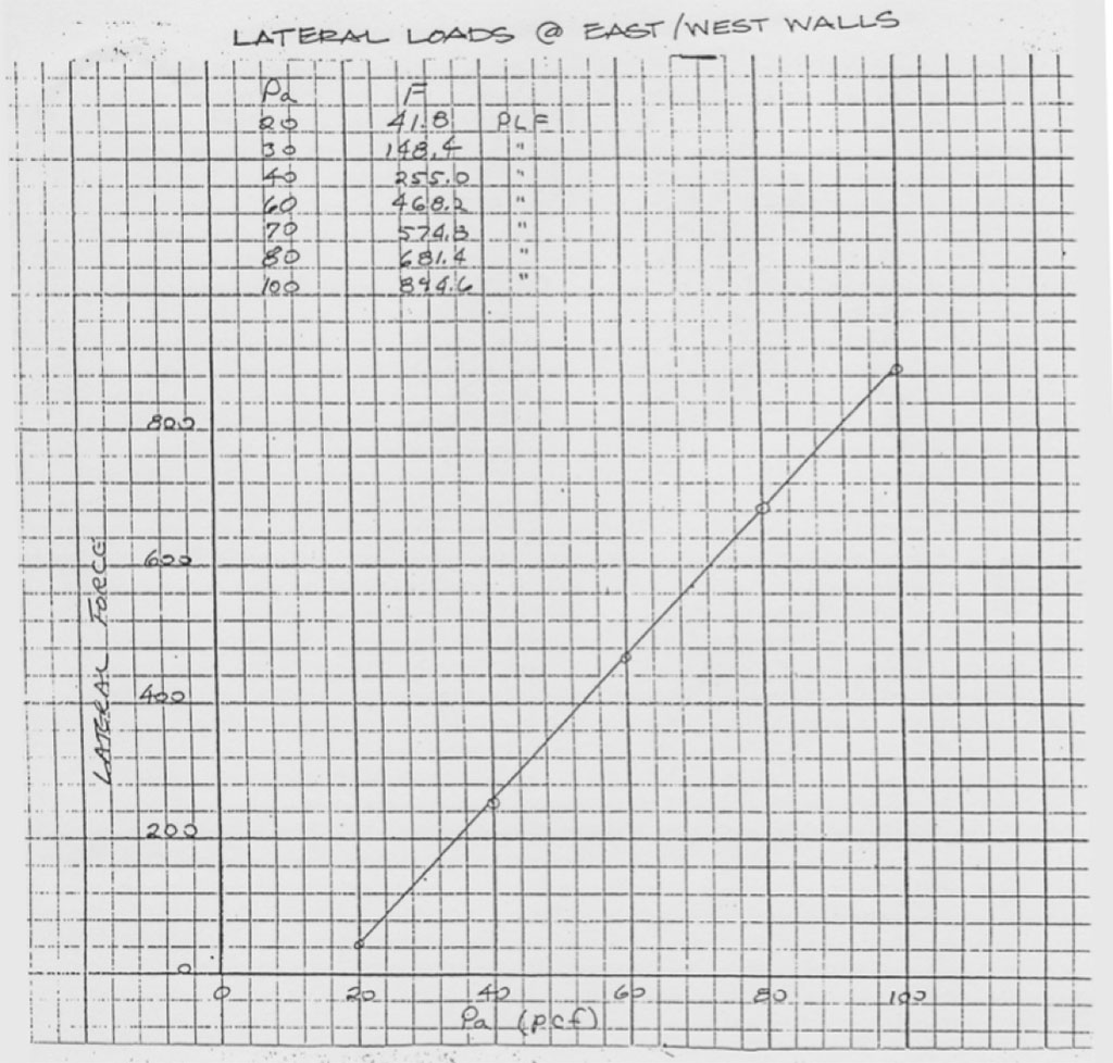
LATERAL LOADS AT TOP OF TIRE WALLS
The tire walls will impart small lateral loads to the roof diaphragm that must be resisted to assure the wall stability. These loads are calculated by a soils engineer based on the soil pressure of each particular site. These loads can be determined from the graphs shown below and on calculation sheets 39 and 40. The first graph is for the walls on the east and west sides of the structure and the second graph is for the north walls. note that the plywood diaphragms will have to be blocked or some other form of additional lateral bracing provided if the lateral loads exceed 285 plf along the walls at least and west ends, or 215 plf along the wall at the north end of the structure.

Buckhorn Geotech Consulting Engineers & Geologists
1990 evaluation of
the Dennis Weaver Project
ENGINEERING EVALUATION OF EARTH-FILLED TIRE CONSTRUCTION DENNIS WEAVER RESIDENCE
RIDGWAY, COLORADO
INTRODUCTION
In the same tradition as the thick adobe walls southwestern Indians built centuries ago, the walls of this massive solar home are designed to keep the interior cool during the day by absorbing the sun’s rays until nightfall when the energy begins to penetrate the walls and heat the home. Non-traditional, however, is the use of tires to support the adobe walls. These tires are packed with adobe earth and stacked flat in a brick-like manner. A sand, straw, and adobe mix is then used as mortar between the tires and as a plaster to cover the wall surface. The walls sere an ecological purpose by providing a use for otherwise discarded tires and an economic purpose in creating the needed mass for passive solar heating and energy conservation.
PURPOSE
The unique building methods and materials have made it necessary to determine the walls’ structural integrity. Tests were conducted to determine the tire-to-tire friction, resistance to failure through sliding, resistance to overturning, and theoretical distribution of soil pressures under a tire wall. All testing was conducted at the building site using actual construction materials and conditions. Two samples of the adobe plaster were also collected and laboratory tested to measure basic strength parameters.
TESTING PROCEDURE
The walls are constructed by placing the tires flat, hand filling with moist earth and packing with a sledge hammer. To determine the lateral stability of the wall, two tests were conducted. First, the tire-to-tire coefficient of friction between packed tires was experimentally determined and secondly, the coefficient of friction between a packed tire and the ground typical of the work site was found. The attached photographs (Appendix A) show how the tire walls are constructed and some of the apparatus used in field testing.
TIRE-TO-TIRE TESTING
A wooden frame pulley and cable apparatus was used for the field testing. The frame served to transfer a known vertical load into a horizontal force on the tire. Two bags of cement whose weight was known to be 94 pounds each and two plastic five- gallon buckets filled with water in one-gallon increments were used to apply the vertical load. The load was gradually increased until movement between the two tires was induced. This experiment was performed on tow typical tires, one 14 inches and one 15 inches in diameter. The tires were handled, filled, and compacted using the same methods and procedures as were being used for the actual construction. No mortar or adobe plaster was used between the tires to imitate a worst-case scenario. The coefficients of friction determined from these tests ranged from 0.728 to 0.877 as shown in the following table.

TIRE-TO-EARTH TESTING
A hand winch and spring scale were used to measure the horizontal force necessary to initially move two different 14-inch tires. The tires were filled and compacted in a typical manner on a level area of soil that was similar in composition and consistency to the foundation soil at the residence. The winch was then used to exert a measured horizontal force on the tire until movement occurred.
The coefficients of friction determined from the two tests were 0.485 and 0.651. These coefficients are significantly less than those measured in the tire-to-tire tests. This shows that it is the properties of the underlying earth rather than the properties of the tire that govern the tire-to-earth frictional resistance to sliding at the Weaver site. The folowing table show typical value for coefficients of friction between various dry surfaces. The tire-to-tire and tire-to-earth coefficients of friction determined in these field tests appear to be reasonable in comparison with these typical values.

TIRE WEIGHING PROCEDURE
Both a 14-inch diameter and a 15-inch diameter tire were filled and compacted using the typical methods and procedures of construction. The tires were then weighed one at a time via two 200-pound spring scales set in parallel. The 14-inch diameter tire was found to weigh 241 pounds while the 15-inch tire weighed 378 pounds.
SOURCES OF ERROR
Any error inherent in the spring scales would have created error in both experiments. However, the scales were tested against the known weights of the cement sacks and were found to be within 3 pounds. It is therefore concluded that the scales were of sufficient accuracy for the intent of the experiment. The wight of the hand winch and scales was estimated at 5 pounds. This amount was added to the load applied during each experiment as compensation for the apparatus.
Small errors may have been introduced by friction in the pulley, weight of the stand, force from pouring the water in the five-gallon buckets, and small inaccuracies in measuring the water and cement bags. These possible errors are considered irrelevant in view of the inherent variability of the construction method. That is, irregularities in the tires and inadvertent sand or dust between the tires would cause larger variation in friction values then would errors resulting from the testing procedures. No attempt was made to quantify these possible variations. Since the tires were “constructed” using the same procedures and methods as employed in construction of the Weaver home, it is felt that results of the tests are representative.
STABILITY CALCULATIONS
After the weights and frictional properties of the tires have been determined, two sets of calculations were made to evaluate the stability of a tire wall. These calculations are attached hereto as an appendix. The first set analyzed a free standing wall constructed of earth-filled tires stacked in overlapping tiers, like bricks. The wall was assumed to retain an earth bank on one side but no lateral bracing was provided on the other side. The second set looked at a similar wall with the addition of lateral bracing at the top, such a would be derived from a roof system, and vertical bracing at each end of the wall, as would be provided through an intersecting wall or a wall return.
The first set of calculations quantified the basic properties of a tire stacked wall in its simplest form. While walls of this type are not used in the Weaver house, the analysis has merit for several reasons. It provides a basis of comparison for understanding the method of analysis, it emphasizes the advantages of lateral bracing and the inherent weaknesses of the free standing wall, and it provides a quantification of the soil bearing pressures beneath the wall that are also applicable to the laterally braced wall system.
The second set of calculations is based on a wall system braced horizontally at the top and vertically at the ends. This represents the conditions at the Weaver house.
Prior to making the stability calculations, the effective width of the tires was determined. This entailed reducing the tire diameter to allow for tread wear and side taper, and then subtracting the fillets between adjoining tires. The net result was a simulated square tire with a width of 18.85 inches for 14-inch tires and 20.42 for 15-inch tires. The weights of the tires were also adjusted to a value expressed in pounds per foot of height per linear foot of wall. The adjusted weight of a 14-inch tire was found to be 123.9 pounds/foot of height/linear foot and the 15-inch tire was 181.4.
FREE STANDING TIRE WALL
Two mathematical models of a free-standing tire wall retaining earth on one side have been established. The models represent equilibrium between active earth pressures behind the wall which act to cause the wall to overturn or slide, and the forces of gravity and friction which cause the wall to resist the sliding and overturning forces. The results of the calculations are shown as curves in Figure 1. The curves represent the amount of lateral earth pressure, expressed as a fluid equivalent, that will just cause a wall of the corresponding height to overturn or slide. It was found that walls under 5- feet high made of 14-inch tires will fail by sliding while walls over 5-feet in height are more apt to overturn. Walls made with 15-inch tires hold the same relationship but the crossover height is about 6 feet. The lateral earth pressures developed by soil can be determined by a soils testing laboratory. They can vary considerably with a general range of 25 to 30 pounds per cubic foot (pcf) for course sand and gravel to over 75 pct for soft silts and clays. The curves of Figure 1 show that a 14-inch tire wall would generally be suitable for a height of up to 4 feet while a wall constructed with 15-inch tires may be stable to a height of 6 feet.
The weight of a tire wall and the overturning moment imparted to the wall by lateral earth pressures create a load on the soil beneath the wall. These soil bearing pressures have been calculated for a free standing wall and are shown in Figure 2. Two curves are shown for both 14-inch and 15-inch tires. They represent the maximum pressure under the outside edge or tow of the tire wall and the overage pressure under the wall. Both curves assume that the lateral earth pressures are at a maximum for the various wall heights shown. Therefore, they represent the upper range of values to be expected under stable walls. The safe bearing pressure of a soil can be established through field and laboratory testing. At the Weaver house, the safe bearing pressure is over 2500 pounds per square foot (psf). However, it can vary in the Ridgway area from as little as 500 psf for soft silts and clays to as high as 5000 psf for gravels and dense soil mixtures.


LATERALLY RESTRAINED TIRE WALLS
The mathematical models developed for the free standing walls were modified to incorporate the additional resistance to sliding and overturning afforded due to lateral bracing. The Weaver house has horizontal lateral bracing from the roof system and vertical bracing from the wall curve at the back of the U-shaped cells and the wall return at the corners of the two outermost walls at the open ends of the U’s. This lateral bracing is transferred through the tire wall via the tire-to-tire friction developed through the overlapping tiers of tires. That is, in order for the wall to fail, movement must occur at each tire between the area of lateral bracing and the point of failure. Therefore, the frictional forces along each of those planes of movement must be overcome. This adds dramatically to the strength of the wall as shown in Figure 3. It can be seen from the curves of Figure 3 that the laterally braced walls of the Weaver house will not slide or overturn.
Although both 14-inch and 15-inch laterally restrained walls are more likely to slide than overturn, it would take lateral pressures in excess of 80 pcf to move a 14-inch tire wall and pressures of over 120 pcf to cause failure of a 15-inch tire wall. The active earth pressures at the Weaver site are expected to be in the 30 to 40 pcf range.
As stated earlier, the soil bearing pressures developed for the free standing tire wall are considered representative for the laterally restrained wall system. The only difference is that the roof contributes an additional axial load to the wall which causes an increase in the soil bearing pressures. At the Weaver house, the full live and dead load to be added would vary from 353 pounds per linear foot of =wall for a 10-foot wide cell to 635 pounds per linear foot for an 18-foot wide cell. These loads added to the loads applied through the tire wall are well within the safe bearing pressure of the soil at the Weaver site.

ADOBE PLASTER
The final analysis conducted at the Weaver house was the sampling and testing of the adobe plaster which was being used to fill the gaps in the tire wall. This plaster consisted of a mixture of native soil (sifted through 1/4” hardware cloth), an equal amount of sand, and about 2 handfuls of straw per wheel barrow load. The dry adobe was found to have a cohesive strength of over 2000 psf. However, the cohesion of the saturated plaster was only about 150 psf. When dry, the plaster can increase the strength of the tire walls by adding up to 21% to the effective tire width. However, should the adobe become wet, the plaster will probably fail under its own weight and all of its strength benefits will be lot. It is recommended, therefore that no structural strength be assigned to the adobe plaster.
CONCLUSIONS
Based on the tests conducted for this analysis and the calculations performed, it is felt that the rammed earth-filled tire walls used in construction of the Dennis Weaver residence near Ridgway, Colorado, will provide safe and dependable support for the structure. The laterally braces walls have sufficient strength from their massive structure and internal tire-to-tire friction to resist the sliding and overturning pressures imparted to the walls from the outside. Additionally, the loads applied to the foundation soils have been found to be well within the estimated safe bearing capacity of the undisturbed soil at the site.
Respectfully submitted, April 30, 1990
Thomas E. Griepentrog, P.E. TEG: dc


